Why Choose a Fuse Clamp for Reliable Circuit Protection?
Why Choose a Fuse Clamp for Reliable Circuit Protection?
A Fuse Clamp provides a firm electrical connection while holding the fuse securely in place. That simple function matters inside control panels, battery systems, vehicles, and industrial equipment. A loose fuse can create heat, vibration, and intermittent faults. In a crowded cabinet, those small problems become difficult to trace.
Electrical protection specialist John D. McDonald often emphasizes, “Protection must be dependable, selective, and fast.” This principle explains the value of choosing a properly engineered Fuse Clamp. The clamp should match the fuse size, current rating, terminal material, and installation environment. Copper or tin-plated contacts can reduce resistance when correctly designed. Strong spring pressure also helps maintain contact during vibration and repeated thermal cycling.
Look closely at the details.
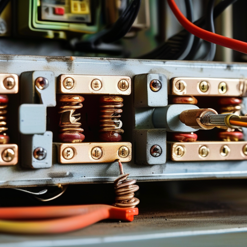
During practical inspections, technicians often check discoloration, looseness, and unusual warmth around fuse connections. These signs may reveal poor contact before a serious shutdown occurs. A quality Fuse Clamp supports safer maintenance because the fuse remains accessible and identifiable. It can also simplify replacement, especially where downtime affects production.
Still, no clamp solves every protection problem. Incorrect wire sizing, weak crimping, moisture, or an unsuitable fuse can defeat a good component. This is where real engineering judgment matters. Specifications should be verified against the equipment manufacturer’s requirements and applicable safety standards. I would not treat appearance as proof of reliability. A polished clamp may still fail under heat, vibration, or fault current.
Reliable circuit protection depends on the complete connection system. A well-selected Fuse Clamp is one important part of that system.
What Is a Fuse Clamp and How Does It Work?
Why Choose a Fuse Clamp for Reliable Circuit Protection?
A fuse clamp is a mechanical holder that secures a fuse inside a circuit. It connects the fuse to the power path through firm metal contacts. When excessive current flows, the fuse element heats and melts. The circuit then opens before damaged wiring becomes a larger hazard. Simple, but not careless.
The clamp also supports safer inspection and replacement. A technician can remove the fuse without pulling loose wires from a terminal. Its spring pressure helps maintain stable contact during vibration, temperature changes, and routine servicing. However, a clamp cannot correct an incorrectly rated fuse. That mistake remains common in field work. Experience shows that poor contact can create heat, even when the fuse itself is healthy.
NFPA’s Home Structure Fires report estimated 35,150 annual fires involving electrical distribution and lighting equipment in the United States from 2015 to 2019. The same report recorded about 470 deaths and 1,100 injuries each year. These figures explain why small connection details deserve attention. IEC 60269 also defines key requirements for low-voltage fuse systems, including performance and safe application. A suitable fuse clamp should match the fuse size, current rating, insulation needs, and operating environment. Check the temperature. Check the torque. Do not rely on appearance alone.
Why Choose a Fuse Clamp for Reliable Circuit Protection? - What Is a Fuse Clamp and How Does It Work?
| Data Dimension | Fuse Clamp | Practical Benefit | Important Consideration |
|---|---|---|---|
| Basic definition | A fuse clamp is a holder or terminal assembly that mechanically secures a fuse and connects it to an electrical circuit. | Provides a stable electrical path while allowing the fuse to be inspected or replaced. | The clamp must match the fuse size, current rating, mounting method, and conductor requirements. |
| Protection principle | The fuse element melts when excessive current produces enough heat to interrupt the circuit. | Limits damage caused by short circuits and sustained overcurrent conditions. | A fuse is a one-time protective device and must be replaced after operation. |
| Current range | Common low-voltage fuse clamps are used with fuse ratings ranging from approximately 1 A to more than 100 A, depending on the design. | Supports small control circuits as well as higher-current power circuits. | The clamp rating must not be lower than the fuse rating or the expected continuous load. |
| Voltage range | Typical low-voltage applications operate at up to 32 V DC, 60 V DC, 125 V AC, or 250 V AC, depending on the approved assembly. | Enables use in automotive, battery, control, lighting, and general low-voltage equipment. | Always verify the complete holder-and-fuse voltage rating before installation. |
| Electrical connection | Spring contacts, clips, or pressure terminals maintain contact with the fuse end caps or blades. | Reduces the risk of an open circuit caused by vibration or loose fuse seating. | Poor contact pressure, corrosion, or contamination can increase resistance and heat generation. |
| Installation style | Available in inline, panel-mount, PCB-mount, DIN-rail, and screw-terminal configurations. | Fits different enclosure layouts and wiring arrangements. | The mounting surface and terminal arrangement should withstand expected mechanical stress. |
| Typical contact resistance | A well-designed and correctly installed assembly generally aims for very low contact resistance, commonly in the milliohm range. | Minimizes voltage drop and unwanted heat at the fuse connection. | Actual resistance depends on contact material, clamping force, current level, and operating temperature. |
| Temperature capability | Many low-voltage assemblies are designed for ambient temperatures around -40°C to +85°C, while some versions support wider ranges. | Allows reliable operation in indoor equipment, vehicles, control panels, and outdoor enclosures when properly specified. | Temperature derating may be required because fuse current capacity changes with ambient heat. |
| Fault response | The fuse interrupts current after its time-current characteristic is exceeded. | Provides predictable protection when the correct fuse type and rating are selected. | Fast-acting and time-delay fuses respond differently; selection must match the load. |
| Maintenance | The fuse can normally be removed from the clamp without replacing the wiring assembly. | Simplifies troubleshooting and reduces service time. | Power should be isolated before replacing a fuse unless the holder is specifically rated for live operation. |
| Safety features | Some designs include insulated covers, touch protection, indicator lights, and keyed fuse positioning. | Helps reduce accidental contact, incorrect installation, and visual inspection time. | Features vary by design and should be confirmed against the installation environment. |
| Best-use conditions | Suitable where compact overcurrent protection, simple serviceability, and economical circuit isolation are required. | Offers a practical balance of protection, accessibility, and installation flexibility. | It is not a substitute for a disconnect switch, circuit breaker, or surge-protection device when those functions are required. |